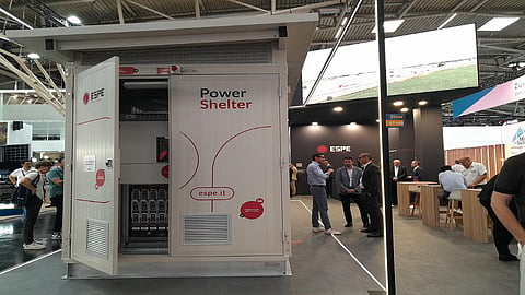

ESPE showcased its resin-insulated transformer-based power distribution system, Power Shelter, for BESS manufacturers and storage project developers, at the show
This system unifies the power conversion components in a single enclosure, reducing shipping and installation & commissioning time
Its 20 kV/800 V MV transformer is rated for up to 2.5 MVA capacity, while the MV and LV panel support operating system voltages of 20 kV and 800 V, respectively
The power distribution architecture of a utility-scale front-of-meter (FTM) battery energy storage system (BESS) differs from conventional commercial & industrial (C&I) and home energy storage systems. It has to account for the high capacity and voltage levels on either the AC or DC side. Such systems comprise a medium-voltage (MV) transformer, switchgear, and an auxiliary panel, facilitating bidirectional power flow between the BESS and the utility grid.
ESPE S.p.A, an Italian turnkey energy system integrator, displayed its Power Shelter, which integrates a transformer, switchgear (medium- and low-voltage), and auxiliary panels on a single metal-based platform, at Intersolar Europe 2026.
This pre-assembled, factory-wired and -tested unit can be transported to utility sites easily rather than shipping individual components. It also reduces on-site installation and commissioning work for integrating storage with the AC grid.
According to the product datasheet, its low-voltage (LV) panel is rated for an AC input voltage of up to 800 V, matching the downstream power conversion system’s (PCS) output voltage. It is placed between the PCS and the transformer’s LV side. The panel uses an upstream main switch with a full-load current capacity of 2,500 A and downstream disconnectors with 350 A fuses. In operation, the disconnectors are closed first, which is followed by the closure of the upstream switch. In the event of a fault on the PCS or BESS side, the downstream fuses will blow first to disconnect the transformer from the grid. While it serves as a first line of safety, the main switch will be opened in response to a large-scale fault signal. In terms of product design, it supports a grid frequency of 50 Hz. Its maximum insulation voltage is 1,000 V, beyond which the panel’s electrical insulation will be compromised.
The MV panel, which connects the 20 kV MV side of the transformer to the grid, is rated for a full-load current of 630 A. Its nominal insulation voltage is 24 kV (AC) and can withstand short-duration peak transient voltage (lightning or surge) of up to 125 kV.
The system’s dry-type transformer core is insulated with resin-based materials. It can deliver a full-load power output of up to 2.5 MVA at a primary voltage of 15/20 kV and secondary voltages of 400/600/800 V. The transformer’s operating temperature is controlled by circulating natural air. It is placed between the LV and MV panels.
The above-mentioned components are housed in a 5,658 × 2,426 × 3,068 mm (L × W × H) enclosure. On top, it incorporates a metal shelter. To protect against rust or corrosion, its galvanized circumference is painted.

